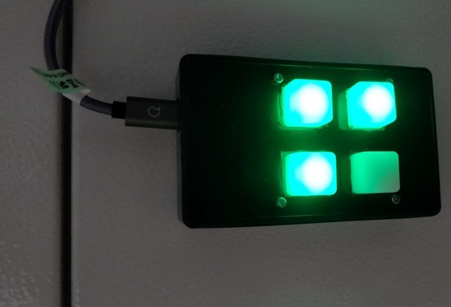
A one glance status light with ESP8266 and Home Assistant
This one glance status light allows to get a quick insight of important metrics retrieved from an MQTT server over WiFi

I have some IoT things that I wanted to manage from one place. I first used Jeedom but I recently switched to Home Assistant which has a nicer UI and a better configuration model (in my opinion of course).
Besides, I always have a memory problem. Sometimes, when I go out or back to home, I forget to switch the alarm on or off.
Moreover, I wanted to have a quick view at the alarm status. And given that, I just multiplied the status lights and even added a few controls.
To give you ideas, here is my usage of it:
- Home mode status (“Here”, “Away”, “Holidays”, “Sleep”)
- Alarm status (“Disarmed”, “Armed”, “Pending”, “Triggered”) – blinks
- Living room temperature by color code
- Next rain (from a service by Météo France which indicates the time before there is rain in the next hour) as I go to work by bike
- Mode selection by button push
- Sonos sound system stop/start by button push
The electronics
The part I like the less is maybe the soldering one. I never have the components I need and when I buy some (with extras) I don’t know what to do with it.
In this case, I gave a try with the ESP8266-12E (aka NodeMCU) development board.
The detailed parts:
- ESP8266-12E development board
- A piece of perfboard
- A 74HC595 8-bit shift register (I don’t have enough digital outputs on the ESP8266)
- 3 resistors somewhere around 70 Ohms to protect the LEDs
- 4 RGB LEDs with common cathode
- Sparkfun’s 2×2 button pad and the associated flexible buttons (https://www.sparkfun.com/products/9277)
- 4 1N4148 diodes
- A project box and some screws 😉
Everything is plugged like in the folowing schematics:
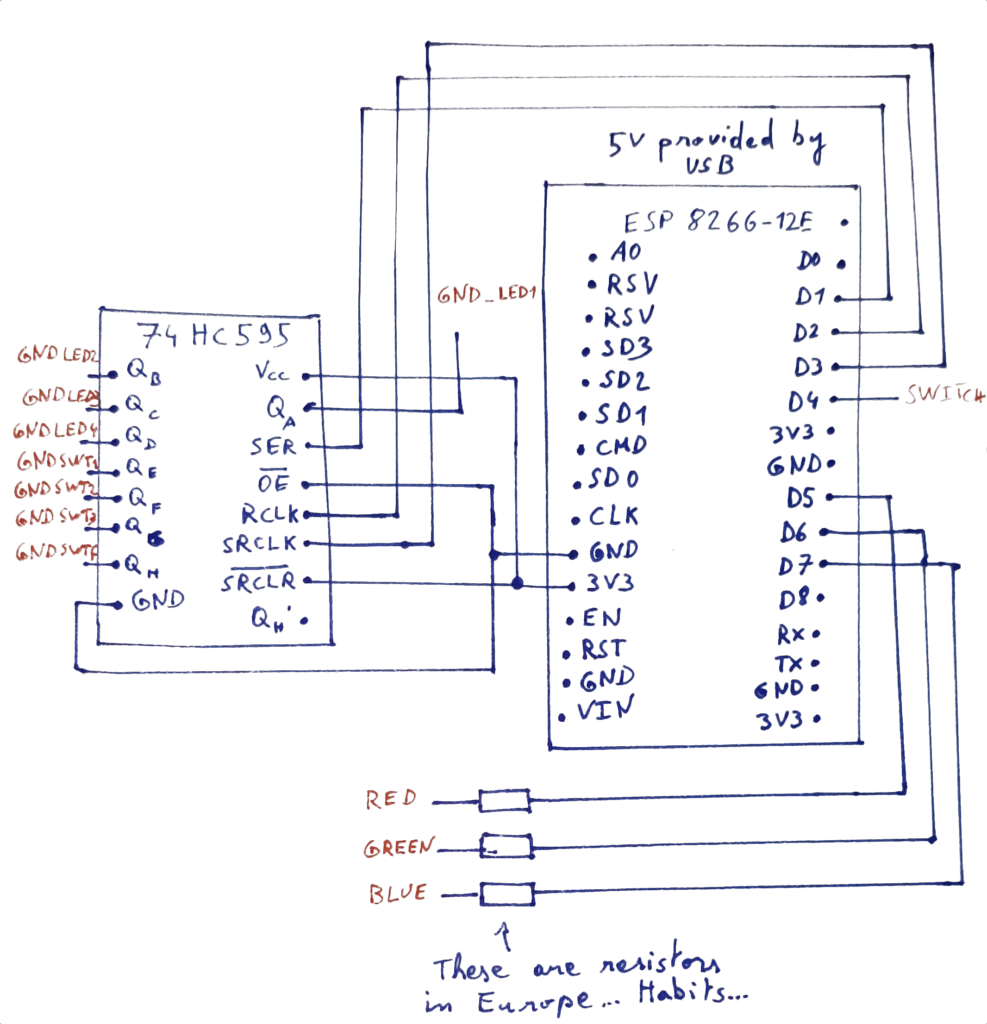
The connections with the 2×2 button pad are represented in red in the schematics.
Note: The 2×2 button matrix is not represented. To know how it should be soldered follow this guide. Just pay attention to the anodes organization of your LEDs. The colors may be in a different order than what is labeled on the button matrix.
To know why numbers are different in Arduino code for digital outputs and input pullups, you should read the ESP8266-12E pinout guide: https://randomnerdtutorials.com/esp8266-pinout-reference-gpios/
The code
My favorite part, because this is where you see the thing becoming alive.
First of all we need to prepare the communications between the button pad and Home Assistant to get some data.
Home Assistant natively supports MQTT servers with the MQTT integration. If you use Hassio, you can even deploy a mosquitto MQTT server directly on your instance.
In the last case, this is really convenient because you can configure the accounts directly in the Home Assistant configuration. For more information, see here: https://github.com/home-assistant/hassio-addons/blob/master/mosquitto/README.md
In the next lines I will assume you have a properly configured MQTT broker and associated accounts and integrations for Home Assistant and your own button pad.
To communicate with the MQTT server with your ESP8266 you will need to install the proper board in the board manager of your Arduino IDE by adding the following URL in the settings :
https://arduino.esp8266.com/stable/package_esp8266com_index.json
In the board manager (Tools->Board Type->Board Manager), install the “esp8266 by ESP8266 community” addon.
You will also need the proper MQTT library. Open the library manager under “Tools” and look for the “PubSubClient by Nick O’Leary“.
Everything should be set up to compile the project!
You now have the choice to create topics that you’re interested in. For each, you will need an automation in Home Assistant to publish data from you sensors.
Here is an example to publish temperature on the home-assistant/temperature topic from a Z-Wave sensor:
- id: 'xxx'
  alias: 'Publish Temperatures on MQTT'
  description: 'Publishes the temperature of the room on MQTT'
  trigger:
  - entity_id: sensor.aeon_labs_zw100_multisensor_6_temperature
    platform: state
  - payload: connected
    platform: mqtt
    topic: home-assistant/button-pad
  condition: []
  action:
  - data:
      payload_template: '{{ states(''sensor.aeon_labs_zw100_multisensor_6_temperature'')
        }}'
      topic: home-assistant/temperature
    service: mqtt.publish
Note: I shared it in YAML for convenience but you can obviously edit this more easily from the Automation editor in the GUI.
The automation above sends the temperature in two cases :
- If the temperature changed
- If the button pad sends “connected” on the home-assistant/button-pad topic.
Note the payload_template argument for the mqtt.publish action. It allows to retrieve states from sensors. You could also use the payload argument to send static text. For more information don’t forget the documentation: https://www.home-assistant.io/docs/mqtt/service/
You can also subscribe to MQTT topics to get updates from the button pad. For example this automation reacts to a message published to home-assistant/set-input-select by modifying the state of the corresponding input select:
- id: 'xxx'
  alias: Set input select
  description: ''
  trigger:
  - payload: Value
    platform: mqtt
    topic: home-assistant/set-input-select
  condition: []
  action:
  - data:
      entity_id: input_select.my_input_select
      option: Value
    service: input_select.select_option
Now that everything is set up on the Home Assistant side, it is code time! Below you’ll find the Arduino code for the ESP8266. The code is explained in comments.
#include <ESP8266WiFi.h>
#include <WiFiClient.h>
#include <PubSubClient.h>
// Network
#define WIFI_SSID "your_ssid"
#define WIFI_PASSWORD "your_wifi_password"
#define MQTT_SERVER "ip_address_of_the_mqtt_server"
#define MQTT_USER "mqtt_username"
#define MQTT_PASSWORD "mqtt_password"
// Shift register pins
#define SER_PIN 5
#define RCLK_PIN 4
#define SRCLK_PIN 0
//How many of the shift registers
#define number_of_74hc595s 1
#define numOfRegisterPins number_of_74hc595s * 8
// Note: the pieces of code handling the registers are adapted from https://www.zem.fr/decouverte-du-composant-74hc595-8-bit-shift-register/
// Input pins for button press
#define SWT 2
// Direct output pins (for LED control)
#define LED_RED 14
#define LED_GREEN 12
#define LED_BLUE 13
// Variables for I/O
boolean registers[numOfRegisterPins];
bool buttons_pressed[4];
unsigned long select_button_pushed_since;
bool debounce_select_button;
WiFiClient wifiClient;
PubSubClient client(wifiClient);
// State variables
float temperature;
void setup() {
  // Init pins
  pinMode(SER_PIN, OUTPUT);
  pinMode(RCLK_PIN, OUTPUT);
  pinMode(SRCLK_PIN, OUTPUT);
  pinMode(SWT, INPUT_PULLUP);
  pinMode(LED_RED, OUTPUT);
  pinMode(LED_GREEN, OUTPUT);
  pinMode(LED_BLUE, OUTPUT);
  //reset all register pins
  clearRegisters();
  writeRegisters();
  // reset the button pressed array
  buttons_pressed[0] = false;
  buttons_pressed[1] = false;
  buttons_pressed[2] = false;
  buttons_pressed[3] = false;
  // Set the timers at zero, this is manual debounce
  select_button_pushed_since = 0;
  debounce_select_button = false;
  // Activate the serial port for debugging
  // You can use the serial monitor with the ESP8266-E12 connected to your host by USB to troubleshoot issues
  Serial.begin(115200);

  // Start network
  WiFi.begin(WIFI_SSID, WIFI_PASSWORD);
  // If your MQTT server port is different, change it here
  client.setServer(MQTT_SERVER, 1883);
  client.setCallback(callback);
}
//sets all register pins to LOW
void clearRegisters(){
  for(int i = numOfRegisterPins - 1; i >=  0; i--){
     registers[i] = LOW;
  }
}
//Sets and display registers
//Only call AFTER all values are set how you would like (slow otherwise)
void writeRegisters(){

  digitalWrite(RCLK_PIN, LOW);

  for(int i = numOfRegisterPins - 1; i >=  0; i--){
    digitalWrite(SRCLK_PIN, LOW);

    int val = registers[i];

    digitalWrite(SER_PIN, val);
    digitalWrite(SRCLK_PIN, HIGH);

  }
  digitalWrite(RCLK_PIN, HIGH);
}
// Sets an individual pin HIGH or LOW on register
void setRegisterPin(int index, int value){
  registers[index] = value;
}
// Scans the button matrix and look for pressed buttons
void updateButtonStates() {
  for (int i = 4; i < 8; i++) {
    setRegisterPin(i, LOW);
    writeRegisters();
    if (!digitalRead(SWT)) {
      buttons_pressed[i-4] = true;
    } else {
      buttons_pressed[i-4] = false;
    }
    setRegisterPin(i, HIGH);
  }
}
// Callback when an MQTT message is received
void callback(char* topic, byte* payload, unsigned int length) {
  // byte* to proper ANSI string conversion
  Serial.print("Received MQTT message: ");
  char* payload_str = (char*) malloc((length+1) * sizeof(char));
  memcpy(payload_str, payload, length);
  payload_str[length] = '\0';
  Serial.print("(topic: ");
  Serial.print(topic);
  Serial.print(") ");
  Serial.println(payload_str);

  // If the topic is the one about temperature
  // The comparison is necessary if you have subscribed to several topics
  if (strcmp(topic, "home-assistant/temperature") == 0) {
    temperature = atof(payload_str);
  }

  // Don't forget to free dynamically allocated memory ;)
  free(payload_str);
}
// Reconnects the MQTT client
void reconnect() {
  // Loop until we're reconnected
  if (!client.connected()) {
    // Create a random client ID
    String clientId = "ESP8266Client-";
    clientId += String(random(0xffff), HEX);
    // Attempt to connect
    if (client.connect(clientId.c_str(), MQTT_USER, MQTT_PASSWORD)) {
      client.setCallback(callback);
      // Signal that the button pad has reconnected
      client.publish("home-assistant/button-pad", "connected");
      // ... and resubscribe
      client.subscribe("home-assistant/temperature");
    }
  }
}
void loop() {
  if ((WiFi.status() == WL_CONNECTED)) {
    // If WiFi is connected -> main loop
    if (!client.connected()) {
      // Reconnect to MQTT if necessary
      reconnect();
    }
    if (!client.connected()) {
      // Fail if the MQTT server is not reachable
      return;
    }
    // Necessary for the MQTT client operations
    client.loop();

    // Reset all registers
    setRegisterPin(0, HIGH);
    setRegisterPin(1, HIGH);
    setRegisterPin(2, HIGH);
    setRegisterPin(3, HIGH);
    setRegisterPin(4, HIGH);
    setRegisterPin(5, HIGH);
    setRegisterPin(6, HIGH);
    setRegisterPin(7, HIGH);

    // Display the temperature button
    // t<19°C: White (Very cold here)
    // 19°C<t<20°C: Blue (A bit cold)
    // 20°C<t<24°C: Green (Perfect)
    // 24°C<t: Red (Hot!)
    if (temperature < 19) {
      digitalWrite(LED_BLUE, HIGH);
      digitalWrite(LED_GREEN, HIGH);
      digitalWrite(LED_RED, HIGH);
    } else if (temperature > 19 && temperature < 20) {
      digitalWrite(LED_BLUE, HIGH);
    } else if (temperature > 20 && temperature < 24) {
      digitalWrite(LED_GREEN, HIGH);
    } else {
      digitalWrite(LED_RED, HIGH);
    }
    setRegisterPin(1, LOW); // The LED n° 2 is used
    writeRegisters(); // Don't forget to commit changes to the register
    delayMicroseconds(50); // A delay to ensure the LED is bright
    setRegisterPin(1, HIGH); // Turn off LED n° 2
    digitalWrite(LED_BLUE, LOW);
    digitalWrite(LED_GREEN, LOW);
    digitalWrite(LED_RED, LOW);
    writeRegisters();
    // Scan the pressed buttons (matrix scan)
    updateButtonStates();

    // Manage the input select button press
    // First debounce it
    if (buttons_pressed[0] && select_button_pushed_since == 0) {
      select_button_pushed_since = millis();
    } else if (!buttons_pressed[0]) {
      select_button_pushed_since = 0;
      debounce_select_button = false;
    }
    // Button debounced? Let's send a message!
    if (!debounce_select_button && buttons_pressed[0]) {
      client.publish("home-assistant/set-input-select", "Value");
      debounce_select_button = true;
    }
  }
  else {
    // If the WiFi is not connected, blink red 2 times/sec
    setRegisterPin(0, LOW);
    setRegisterPin(1, HIGH);
    setRegisterPin(2, HIGH);
    setRegisterPin(3, HIGH);
    setRegisterPin(4, HIGH);
    setRegisterPin(5, HIGH);
    setRegisterPin(6, HIGH);
    setRegisterPin(7, HIGH);
    digitalWrite(LED_BLUE, LOW);
    digitalWrite(LED_GREEN, LOW);
    digitalWrite(LED_RED, HIGH);
    writeRegisters();
    delay(250);
    digitalWrite(LED_RED, LOW);
    delay(250);
  }
}
I use this for several metrics and it works like a charm! At one glance you have an idea of the status of your important information for your home.
Have fun with this 🙂